Normal Maps: Can Somone Explain This "Black Edge" issue
polycounter lvl 16
Hi All,
At the start of this weekend I had a list of normal issues that I was hoping to resolve and so far polycount has helped me with all but one. You guys are awesome, I don't know what I would do with out this community")
My last issue I'm trying to wrangle with is why black borders along certain UV border edges.
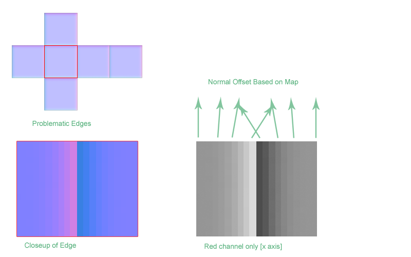
In this write up Ariel Chai shows the following issue:
He explains that:
From the sounds of it, for some reason, the shader is simply sampling the wrong pixels. However exactly what's going on eludes me.
I am able to reproduce the issue in Xnormal:


I'm basically trying to figure out the anatomy of the issue. What about those particular edges is making the shader "sample" the wrong pixels, and why would it be doing this in the first place.
My intuitive understanding of what should be happening is that the pixels would be sampled like any others and receive the same lighting information.
I accept that breaking up the UVs fixes this, I would just really like to understand why.
At the start of this weekend I had a list of normal issues that I was hoping to resolve and so far polycount has helped me with all but one. You guys are awesome, I don't know what I would do with out this community
My last issue I'm trying to wrangle with is why black borders along certain UV border edges.
In this write up Ariel Chai shows the following issue:
He explains that:
The problems occurs because each face normalmap points to a different direction as illustrated below.
Even if the uv edge is exactly between the pixels, the way those pixels would be pulled by the realtime renderer will mix them up resulting in a sharp normal transition which stands out from the rest.
From the sounds of it, for some reason, the shader is simply sampling the wrong pixels. However exactly what's going on eludes me.
I am able to reproduce the issue in Xnormal:
I'm basically trying to figure out the anatomy of the issue. What about those particular edges is making the shader "sample" the wrong pixels, and why would it be doing this in the first place.
My intuitive understanding of what should be happening is that the pixels would be sampled like any others and receive the same lighting information.
I accept that breaking up the UVs fixes this, I would just really like to understand why.
Replies
The only way to avoid this is to either move your UVs apart (create UV seams along the hard edges), or soften the edges.
It'll become more obvious with mip-mapping too since then the "bleed" will be exacerbated.
This morning, on my way into work, I had this finally click for me. The issue, in part, is the direction the rays are cast. When you are not using a cage the rays are controlled by the smoothing (angle of the vertex normals).
This means if you have a hard edge at a 90 degree angle your rays will be shot out of the polygons perpendicular to the surface. This means every pixel on that surface will be expecting to be facing perpendicular to the face on which it rests.
However texture bleeding means that those pixels will get shifted, 90 degrees in this case, when they bleed between the faces.
If you use a cage this will reduce the issue because the rays will be cast in such a way that the resulting pixels wont be expecting to be perpendicular to the surface which gives you a bit more leeway with texture bleeding. It will still produce errors, they just wont be as noticeable.
Ultimately texture bleeding is always going to be an issue with normal maps, but its a lot worse when the rays are cast perpendicular to the surface rather than at an angle.
What I was trying to say in my explanation was that, when you use a cage, it can be like baking with averaged vertex normals. This means the difference between the normals of the adjacent pixels (that are getting mixed and causing the problem) is less. Because the rays are being cast around the corner rather than perpendicular to either face (man this stuff is really hard to describe with just words).
I wasn't trying to say that a cage would fix the issue at all, just that it might make it slightly less noticeable. Is that a correct statement, or have a missed something, I think I might have
Anyways, I didn't want to drag this out, but I wanted to make sure I properly understood this before I moved on.
A. When you use an averaged cage on a mesh, you will not get any "gaps" or missed detail from the unwelded vertices that result when you use a hard edge on your low. This can appear to be a similar problem to the other thing, but is *entirely* different.
B. When you do not split your uvs, but split edges on your lowpoly, what you're getting is essentially two drastically different normal directions(both sides of the same edge) trying to draw on the same pixel. You thus get an averaged result of the two, pointing in a totally broken direction.
Using an averaged cage will fix the first problem, but will do absolutely nothing to help the second, in any situation. However it is possible to do both of these and get a double-broken result. So perhaps you were doing that and saw some improvements when you fixed the first issue.
Heres an image.
1. Correct method, averaged cage, UVs slit at every hard edge.
2. Broken, point A above, we've solved the cage problem, but the uv problem still exists.
3. Broken, point B above, we've solved the UV problem, but the cage problem still exists.
4. Double broken, both cage and UVs are set up poorly.
That was very informative, thanks for posting it. One questions though. Is this such a problem with your new quality normals modifier/shader? i dont seem to be suffering from this issue and i havent been splitting my uvs (using ray distance to bake) Does this only count when using smoothing groups?
So my understanding now is that hard edges create "gaps" or missed rays, and that is one issue.
What I don't understand is this:
I have my UVs directly in between the pixels. So why then does the baker mix them? It would make sense if the UV edge was half way on and half way off, but its directly in between them. I guess I'm having trouble wraping my head around why the baker is still mixing the values in this case.
Hey r_fletch_r, as far as I know the "quality mode" fix doesn't do anything new. These issues exist in all game engines. Its just that the tangent basis between the 3dsmax baker and its viewport renderer are off. So the math within max wasn't syncing up.
This caused any problem in your normal maps to become worse, it doesn't solve any fundamental issues it just stops max from poring salt on an open wound.
Just a note of clarification about where I am coming from. This issue appears to be happening with mip mapping turned off. I think this is really just me being ignorant of how exactly these two pixels are being "mixed". If anyone can explain how/why the mixing is occurring I think it will clear this all up for me.
This issue is still the same with Quality mode, its down to the limitations and content of the image/resolution so its not really something we can fix.
jocose:
If you can force unfiltered textures you may see a correct result with uvs snapped perfectly like that, its not only a mipping problem but a problem in that texture filtering "blurs" all of your textures, so those pixels are still getting blended together. If it is still an issue after that, you've got me stumped, as how i've always understood the problem is that the two very distinct normal directions blend together and create a normal that is incorrect for both sides of the edge.
i hope this isn't getting off topic but i ran my own tests when i was taking a break from work on thursday and ran these similar tests. then i tried doing tests with a box that had chamfered edges. how would you go about getting good normals out of that? where exactly would you split the uvs and is there any way to get parts of the box seamless as in the edges are sown together kind of like how jocose had in his first example?
hope this made sense O_O but i was having a problem with a box that had chamfered edges and trying to bake a normal out of the high res, yet the edges came out funky. when i get on my pc later on tonight i'll see if i can post examples of my problem.
In maya, under advanced settings you can select either "surface" or "geometry" normals, i dont remember which is which, but one is averaged and the other is not, experiment there and you'll figure it out.
Poly's at angles that are 80 adn bellow shouldnt be of the same smoothing group. this rule is very general, so it doent apply as well in other area. chamfering key edges helps if you want to make the the same smoothing group. racer made a great tut. watch it.
http://cg.tutsplus.com/tutorials/3d-art/how-to-bake-a-flawless-normal-map-in-3ds-max/
roosterMAP - oooo I've seen his gun tutorial but I take it this one goes more in depth with baking out normals? Thanks for the link.
this one isn't as basic though it contains a lot better information: http://cg.tutsplus.com/tutorials/autodesk-3ds-max/project-workflow-creating-a-next-gen-sci-fi-prop-day-2/
I just wanted to post back here. I made another post over at GameDev.net and posted this issue. After I uploaded a test file one of the members there was kind enough to test it out for me and confirm that the issue is the result of bilinear interpolation.
He also was kind enough to post an explanation of how it works.
Here are some pics:
Bilinear Interpolation:
Linear Interpolation:
I didn't actually understand what Bilinear interpolation was. Which was a big part of why I was so confused. Venezon on gamedev.net explained it like this:
Normally texture filtering wont ever cause a problem provided your tangent space is continuous (meaning you all your normals are averaged). This is because all pixels will always have neighboring pixels whose color values reside on the same space and are there for continuous (have similar color values).
The issue comes about when we break continuity (introduce a hard edge). This is because the baker correctly assumes that space ends at that hard edge. Meaning that one polygon isn't smoothly interpolated to the next. This creates a major difference in the color values that get baked (a difference that would have never occurred had our tangent space been continuous).
By having two values that are so different next to each other we open ourselves up for trouble. Once bilinear interpolation is applied the values get blended and we get a normal pointing in a crazy direction.
This is why we add in the edge padding to basically manually say "don't interpolate this". I suppose you could just think of it as a hack to get around bilinear interpolation which is usually our friend, but is in this case is our enemy.
Don't know if that helps anyone, but I know feel like I have an intuitive understanding of the issue and also learned a thing or two about texture filtering.
Here is the GameDev post in case anyone is interested: http://www.gamedev.net/community/forums/topic.asp?topic_id=574157
I agree with you there. It's always a case to case judgement. And splitting/hard edges generates more vertices, still the texture will be a lot more "reusable" if there aren't as many huge gradients on the shells in the texture. If you have a few pretty basic shapes in your texture you'll be able to reuse those a lot easier if they don't have a concave shaped normal over the whole shell.
When I work with big modular sets I can reuse parts of the texture ridiculously many times but for different objects, not always just copied shapes, and it is here I can really make use of the texture parts more if they are not uniquely made for a certain shading.
But yeah, very case sensetive
I am fairly certain that EQ has an entire hard drive of images and text docs dedicated to this subject alone.... ready for any and all new normal map threads that arise since his expertise can be found in almost every one of them. The guy needs a break people. :P
I think you understood it wrong: i didn't split the vertices - i just split the UVs. The verts are welded together BUT:
I programmer told me some time ago, that the model is split by code where different smoothing groups hit together. Means:
thanks for this thread jocose, so my question is...if i split the uvs and average normals to get clean results on this hard poly stuff...then i have gaps in my texture. i see the work that has to be done to get this to bake correctly, but in the end, now we're going to have a lot of texture gaps. oy...am i missing something?
Yes, Neox is quite correct here. But the thing to keep in mind is, if you were going to use hard edges anyway, splitting your UVs will add no extra verts. A uv split alone = 2 verts, a hard edge along = 2 verts, and both together also = 2 verts.
Some people will try to make the argument that you should just bevel the edges instead of using hard edges as the vertex hit can be around the same, but ignore the fact that triangles are not free, and that long-thin triangles can be a bit of a bottleneck when rendering.
If by gaps you mean breaks in the continuity of the rays projected out of the low poly mesh during baking, then there is a quick fix for that: Use a cage.
If by gaps, you mean general seams in your textures then yes you will, but keep in mind this issue only occurs along very sharp angles, and usually you want to planar project your UVs along co-planar faces. So I often find that my nearly ideal UVs (low distortion) just so happen to coinside with my ideal UVs for baking normals (split edges along sharp angles).
If it really becomes an issue for you then just use bevels instead of hard edges. It will make your model look better up close anyways and will have the same result. Its just less efficient.
In the end you have all the options you really need, you just have to weight it all out and makes some informed decisions.
I wanted to make a new thread, but I guess I cant atm, so I hope its okey that I ask this here. Ive been trying to learn how to create decent looking normal maps from hipoly source for the past few days and get problems that I dont think I can solve myself, so sorry for asking those noob questions.
What I did was create a simple hipoly and lowpoly test mesh split the uvs where I have hard edges, added projection, reset it and did a small push so all the model is covered, then baked the thing out and this is what I got (using max RTTnormalmap shader).
http://sleekupload.com/uploads/5/problem1_2.jpg
It looks pretty good from a distance but close up you can see the problem where the hard edge is, it should not be the error that is from pulled pixels because my uvs are split at that part. Heres how the uvs and lowpoly look.
http://sleekupload.com/uploads/5/normalmap.jpg
http://sleekupload.com/uploads/5/lowpoly.jpg
The other problem I get and Im not sure by it is like that is that the round thingy I modeled in the hipoly gets distorted when baked down and I dont understand why it is like that if the cage is pushed out evenly in all directions, heres what I mean.
http://sleekupload.com/uploads/5/distortion.jpg
Again sorry for those noob questions.
Here is a test I did to elaborate further. These tests where baked in xnormal 3.17.4 with cages (for some reason 3.17.5 does not read cages properly).
Thanx Ya
You get black edges if you don't bake with a cage AND if you don't have enough padding between split UVs.