Noob Learning Challenge, Dark Aribeth (NSFW)

polycounter lvl 9
0. Introduction
This document is aimed at newer character artists who may be unsure on their design process in regards to making a game ready character, or who are looking to learn some different workflows. I feel I have learnt so much since joining polycount, and socialising with other artists on Google Hangouts, that I would like to return the favour and help some of our less experienced members.
1. Pre-Production - Research
The first issue I came across was deciding what I wanted to make. But luckily I have internet, games, books, sketchbooks, inspiration folders, and other things to help me out (I highly recommend creating a scrap book/folder/collection of some sort to hold the multitude of awesomeness you will come across during your time as an artist). After looking through some books and inspiration folders, I went online and browsed through www.CreativeUncut.com and found some concept art of Aribeth from Neverwinter Nights. I thought this would be an interesting character to do because she is from an old game I was very fond of, and now I could create a modernised tribute to her with my own creative influence.
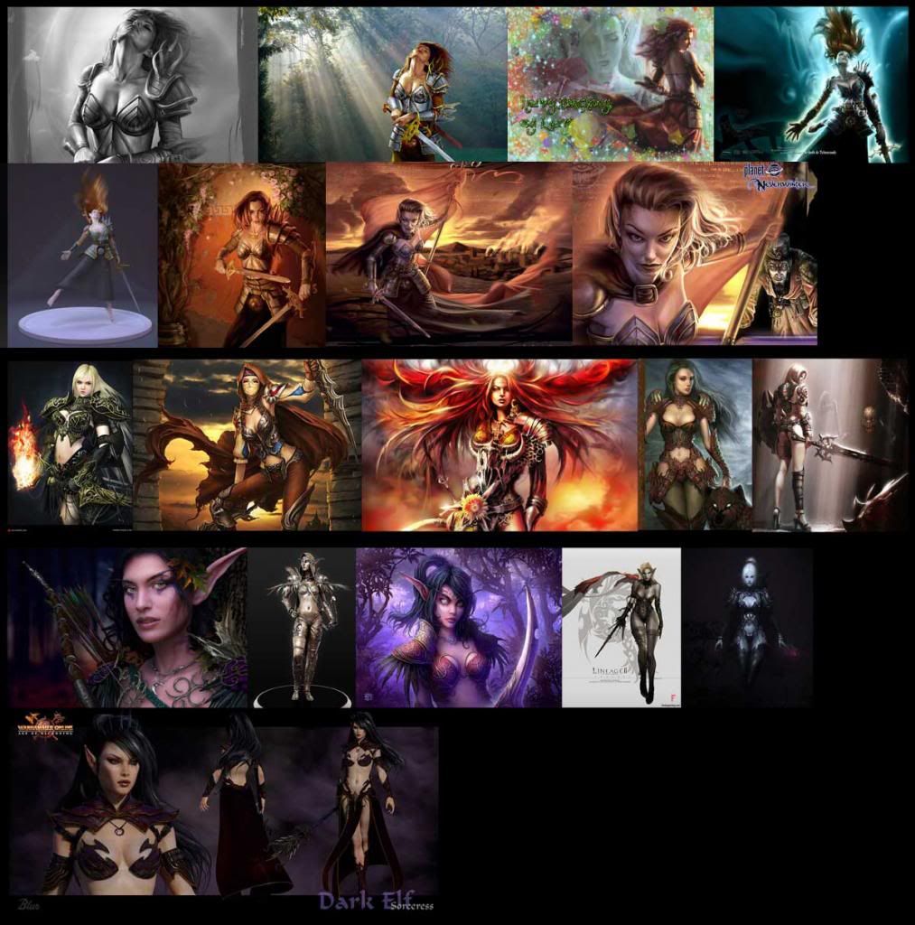
I compiled a folder full of images, which I worked into a research board. I initially sourced images which were professional concepts or fan art of Aribeth, as well as other female warriors who resembled her style. I also wanted to find a unique twist to the character, to make her special and stand out from all the other recreations of her image. The TWIST!
I began by researching who she was, what was her story, what traits made her stand out, and I was reminded by a friend that towards the end of Neverwinter Nights she turned from an elven paladin into an evil badass, a Dark Aribeth. I was intrigued by this idea, and wanted to take it further. I explored the darker side of the elven race, looking at dark elves, drow, and night elves. Their clothing, colours, patterns, and symbols really stood them apart from the average vanilla elf, so I chose to use this as my twist.
It was also important to consider what were the common perceptions with this type of character and how has it been stereotyped in the past. With this information I could pick and choose which traits to keep, so that the character would fit her racial and social type, without becoming generic.
Google Hangouts was an excellent source of information for finding out opinions and lore on this subject, and speaking with other artists and gamers really helped with my research process. With this extra information, I added more variety to my research board, and the main research stage was complete!
I would like to thank Caldria for sharing his knowledge on Neverwinter Nights, almighty_gir for finding me some awesome images, and pestibug for his insightful rant on the historical relationship between Elves and Orcs!
This document is aimed at newer character artists who may be unsure on their design process in regards to making a game ready character, or who are looking to learn some different workflows. I feel I have learnt so much since joining polycount, and socialising with other artists on Google Hangouts, that I would like to return the favour and help some of our less experienced members.
1. Pre-Production - Research
The first issue I came across was deciding what I wanted to make. But luckily I have internet, games, books, sketchbooks, inspiration folders, and other things to help me out (I highly recommend creating a scrap book/folder/collection of some sort to hold the multitude of awesomeness you will come across during your time as an artist). After looking through some books and inspiration folders, I went online and browsed through www.CreativeUncut.com and found some concept art of Aribeth from Neverwinter Nights. I thought this would be an interesting character to do because she is from an old game I was very fond of, and now I could create a modernised tribute to her with my own creative influence.
I compiled a folder full of images, which I worked into a research board. I initially sourced images which were professional concepts or fan art of Aribeth, as well as other female warriors who resembled her style. I also wanted to find a unique twist to the character, to make her special and stand out from all the other recreations of her image. The TWIST!
I began by researching who she was, what was her story, what traits made her stand out, and I was reminded by a friend that towards the end of Neverwinter Nights she turned from an elven paladin into an evil badass, a Dark Aribeth. I was intrigued by this idea, and wanted to take it further. I explored the darker side of the elven race, looking at dark elves, drow, and night elves. Their clothing, colours, patterns, and symbols really stood them apart from the average vanilla elf, so I chose to use this as my twist.
It was also important to consider what were the common perceptions with this type of character and how has it been stereotyped in the past. With this information I could pick and choose which traits to keep, so that the character would fit her racial and social type, without becoming generic.
Google Hangouts was an excellent source of information for finding out opinions and lore on this subject, and speaking with other artists and gamers really helped with my research process. With this extra information, I added more variety to my research board, and the main research stage was complete!
I would like to thank Caldria for sharing his knowledge on Neverwinter Nights, almighty_gir for finding me some awesome images, and pestibug for his insightful rant on the historical relationship between Elves and Orcs!
Replies
If you want to be a character artist, you need to learn and practice anatomy. Pull out your sketchbook or tablet and start drawing. If you are not sure where to start, there are plenty of resources available to you. Polycount has a lot of threads on the subject, and CGTalk has a dedicated forum for people learning and improving their knowledge of anatomy:
Artistic Anatomy and Figurative Art
Some of the forum leaders have incredible talent when it comes to traditional art, so you can really learn a lot here.
It is common for people to have difficulty getting pen to paper, usually because they find drawing to be a weakness. ANYONE can be good at drawing, you just have to practice. If you are serious about being an artist, the time you spend now will definitely pay off. Im not a confident drawer myself, but the more I do it, the more I enjoy it, and the better my art gets.
Joe March has been kind enough to have started a sculpting training thread on polycount, where he will take you through an artists anatomical study of the human body. I have personally taken part in his classes, and he is both an excellent teacher and an accomplished artist. Keep subbed to this thread:
POLYCOUNT G+ HANGOUT SCULPTING TRAINING!
Here are a few studies I made:
Depending on your workflow, you dont need to spend too much time on this stage, but it has its benefits. Firstly, it means you will have a better base mesh for future projects which should help you during the sculpting stage. It also helps you develop a better understanding of how topology works with smoothing and animation, and which edge loops can give you a good start when sculpting (especially when sorting your polygroups).
What I like to do is take a base mesh from a previous character, analyse how the topology worked during the sculpting stage, and improve on areas which caused problems. The main areas which concerned me were the topology with triangles, and vertices with 5 or more poles. A good way to judge how they will look during subdivision is to apply smoothing (NURMS Subdivision in max, smooth preview in Maya) and see if areas pinch and crease. You might find it difficult to smooth these areas in your sculpting program, so its best to avoid them.
The use of NGONs is a controversial subject, but some well-placed NGONs can benefit your model, so experiment. They are not ideal, but if used properly, can produce better results than triangles (thanks to almighty_gir for his tips on the subject). What Ive noticed is that if you smooth your model before exporting to a sculpting program, youll get more predictable results. If you bring it straight into ZBrush it will convert 5sided ngons into a quad and tri, but it may break the symmetry. There is an interesting thread on the subject by Steven Stahlberg, which you can find here:
Body topology
The polycount wiki is also full of useful information on this subject:
CategoryTopology
below is an image with a few more subdivision and a basic layer of polypaint:
After mulling over some ideas from the research stage, it was time to work out my design. I didnt want this to be a carbon copy of an existing Aribeth, I wanted to make something a little different - more to my taste. I went over my research board and look at which parts of the original Aribeth designs were suitable. Which parts did I need to make a strong connection with the original character, while still being able to exercise some artistic flair?
After I highlighted the parts that I wanted to use, I could look at my next stage of research, female warrior. I went over and picked out which parts I wanted to use in my design. These were smaller design features that added to the character as opposed to define it. Finally I consulted my twist research: the dark elves. What made a dark elf different, what common symbols or imagery did they use? Apart from their hair which tends to be very dark or very light, they can be defined by accessories, symbols, and markings. They seem to favour contrasting hot and cold colours, as well as darker attire with bright trims. Obviously different stories have different lore regarding dark elves, but I think I had enough to go on for this to affect my character.
Painting and concept arent my strongest skills, as 3D art is my focus, but every time I start a new project I seek to challenge myself, and this would be part of that challenge. If youre not challenging yourself, youre not learning! I found this stage of the process tough, but very rewarding. Thankfully my friends on Google Hangouts were very helpful, and I would especially like to thank josephsilverman and Jessie Lam for their paint-overs and helpful advice.
below is the first concept iteration which I decided not to use:
and these are the revised concepts which I used:
With my concept complete, I could now work on the armour and clothing for my base mesh. This stage is can be tackled in different ways: some people like to start in a sculpting program such as ZBrush, others in a polygonal modelling program like 3ds Max. Personally I prefer fully preparing my model in Max as I find it easier to position simple shapes using its tools and viewports, as well as prepare Hard Surface objects for sculpting.
I paid special attention to keeping clean and even topology so that the meshes would subdivide nicely in ZBrush. Whenever I felt I had to use triangles, I would test them out using a Turbosmooth modifier (NURMS subdivision works fine too) and check for pinching and creasing. I also added control edge loops where I wanted the edges to hold their shape, so that they wouldnt just smooth into a C-curve. Try not to make the topology too dense at this stage otherwise you may have less control with deforming large shapes in your sculpting program.
It is worth considering preparing certain objects for polygroups in ZBrush. For example, my belts and sash overlapped themselves, meaning it could be time consuming to manipulate separate elements in ZBrush. To tackle this issue I created separate UV islands for different sections of a mash in 3ds Max, and when I imported the objects into ZBrush, I selected Auto Groups with UV under the polygroups option. This grouped those divisions, so that the mesh would still be whole, but I could select and mask off specific areas for better control. There are other ways to do this, but I found this method quick and easy.
One of the Hard Surface issues I faced when preparing the base mesh, was applying bolts to a round surface, such as the torso armour. I could apply these bolts manually, and mirror them to the other side, but this could be very time consuming. Luckily I was on Google Hangouts when I was tackling this problem, and I was advised to create a spline which could be used as a path to constrain repeating objects. I did this by selecting existing (and new but temporary) edges from the object the bolts would repeat over, and converting this selection to a spline (in 3ds Max this is Create Shape from Selection). I selected a bolt I made earlier, and clicked: Tools> Align> Spacing Tools. This brought up a small window. From this window I clicked Pick Path and then selected my spline. This automatically added some copies of the object to my spline. Then I just added a few more to the count until I had the necessary number of bolts surrounding my geometry. Now my bolts were evenly placed, so I just moved them slightly into the correct positions. Thanks to metalliandy for his help!
this is the spline spacing tool:
and below is the base mesh in ZBrush:
I've prepared notes and mini tutorials for how I tackled some of the sculpting and retopology process, and I will try and write up and post the documentation after Animex and the London Meetup (which is next week).
I really must learn to sculpt very well to create something this cool.
@PyrZern: Thankyou! I hope my next write up well help give you some sculpting inspiration
There are a few rules and practices I adhere to when sculpting in ZBrush, so Ill start by sharing a few. Firstly, you should concentrate on the initial forms and silhouette of your sculpture. This means staying on lower subdivisions, and making the Move Brush your best friend! If you start detailing too early and realise there is a problem with the shape and form of your character, your time spent detailing may be wasted when you have to deform its overall shape.
Secondly (and this may be more of a preference) build in layers! For example, if your character has clothing under their armour, build that first. This will give you a better understanding of the volume of each shape, and how they should fit together. It will also help avoid intersecting geometry, which could cause you problems down the line. Later on you can merge the SubTools if you want, and build multiple SubTools as a single piece when you make the low-poly.
Thirdly, use Polygroups! Polygroups are a fantastic feature that allow you to split your mesh into manageable chunks, which you can select, mask, and isolate at any time. You can use these in areas like your mouth, so you can select the lower part of your mouth and open or close it without moving the upper part of your mouth. Polygroups are very helpful for speeding up your workflow.
Finally, switch materials! If you stick to one material, such as MatCap Gray, your model will be displayed in a particular way, so you might not notice unwanted deformations in your models. Switch materials every so often to properly understand the surface and shapes of your mesh. Basic Materials are great too because they will react to custom lighting, so feel free to experiment with them!
Sometimes what works in a 2D concept wont work as well in a 3D model. This is a common issue when sculpting from a 2D reference, but it should only be a minor hindrance. For example, when I was constructing my leg armour I realised that the layering didnt make sense in 3D space. This resulted in bulky shapes, which had a negative impact on the silhouette of my character. I didnt notice how weird it looked until a friend pointed it out (this is a reason why Google+ hangouts can be so useful).
I went back to my original concept and began to paint over in Photoshop. Harford was kind enough to have given me a paint-over which significantly improved the silhouette of my character. Instead of creating a base mesh like I did for the rest of my model, I decided to concept this piece within ZBrush itself (I got the idea from the EAT3D Hardsurface 2 tutorial). I used a sphere with Dynamesh active to sculpt the shapes, mainly using the Move and ClayBuildup Brushes. Once I was happy with this I quickly retopologised it in 3ds Max (also adding some control edges) and brought it back into ZBrush. Now I could sub-divide the mesh and get crisp, clean results. I also used ZSpheres to make the pattern on the front of the leg guard, made an adaptive skin from them, and used the TrimDynamic and hPolish brushes to get the clean, hard-surface shapes I wanted.
I would also like to thank Caldria and Joe March for giving me some ideas to redesign the skirt. Unless you have a strict concept to follow, you should try and evolve your character during this process. Use the concept as your guideline, but feel free to experiment. Be creative, you are an artist after all!
I believe it is important to try new things and experiment in every personal project you take on. Using ZBrushs Surface Noise deformer was one of these experiments. I was introduced to it while watching an EAT3D tutorial and made my own workflow to suit what I was doing. I want to share some of this process because it was a really fun tool to use!
I selected the mesh where I wanted to add the deformation, and masked the area I wanted to deform.
I then extracted this selection using: SubTool>Extract, and experimented with the thickness before committing and clicking accept.
I wanted an even distribution in my geometry so that I could efficiently divide it to a high level, so I used QRemesher (Geometry> QRemesher). This cleaned up the extracted piece with an even quad distribution. I subdivided the mesh to give it enough resolution to deform correctly. I also stored a morph target (which can be useful later on. Ill explain further down).
I selected the NoiseMaker Noise11.ZNM under Surface>Lightbox>NoiseMakers, and double clicked the icon to load it (this previews a projection on your model, so it may not look exactly like this when you apply it).
In that same surface menu, I selected Noise and adjusted the size setting (it previews the result in the side screen).
Once I was happy with the result I clicked Apply To Mesh.
Now it was time for my Morph Target to shine! I pressed Switch (under the morph target options) and it reset my mesh to what it looked like before I applied the transformation. I then selected my Morph Brush from the Brush palette and started painting on my mesh. This brought out the noise details from its complimentary Morph Target. Using this process allowed me to paint the deformation with a high degree of control. This way I could, for example, paint around the bolts while leaving enough clean space to apply an Alpha!
[FONT="]The first one I would like to mention is creating a damage pass using Morph Targets. This was a process shown to me by [/FONT][FONT="]metalliandy and it is rather awesome! It involves creating a morph target and a series of layers. In each of these layers you will basically beat the hell out of your mesh, leaving it heavily deformed. You can then adjust the effect of the layers, and paint with the Morph Brush, to reduce the damage to an acceptable state. This process is both efficient and really fun! I would explain the process in detail, but metaliandy does an excellent job of that in his video:
[/FONT][FONT="]http://eat3d.com/free/zbrush_stone[/FONT][FONT="]
[/FONT]
Another useful technique is using the SliceCurve Tool to create seams in clothing. Use the SliceCurve Tool while using Dynamesh (with Groups highlighted) to split a mesh into multiple pieces. If you turn on PolyFrame you can see how the mesh has been split. You can then use a combination of Smooth Brush and Inflat Brush to refine this area and get the desired result (I learnt this technique from Mike Jensens HardSurface 2 Tutorial).
One final tip I wanted to share is something I learnt from Harford. Creating realistic eyelashes is an important step when analysing your characters face (especially with female faces). Having good eyelashes will help you decide if the face is working well or not. There are a few good ways to create eyelashes. For example, you can use 3ds Maxs Hair and Fur tool, or model the eyelashes individually using Splines, and then import them into ZBrush. You can also use these eyelashes later on by baking them into a low-poly plane, giving you detailed and efficient results.
Well thats it for Highpoly production stage! I will try and post the Lowpoly stage soon. Thanks for reading, and feel free to ask any questions or comment on my workflow.
I don't know if it is just the camera angel but it seems like there is one renegade eyelash on the upper right eye lid, it is not a big issue though haha
Thanks for sharing the stuff about the Noisemaker there are some really useful tips in there and it makes me really wanna have a play around in there myself.
Thanks guys! I appreciate the support. Writing documents is not the most fun thing in the world, but if people find it helpful then it is worth it. I'll post the following chapters now...
Retopology is the process of preparing a low-poly/game-ready mesh, based off a high-poly mesh, which can be used for real-time rendering and animation. During this stage correct topology is a key concern. The topological flow must work with the potential animation of the character, and it should also be efficient. Using too much resolution can be wasteful and make things difficult when the character is being skinned and weighted.
A common mistake is using too much resolution with the belief that the mesh needs it to deform correctly during animation. I found a video that shows how little resolution you need to create smooth animations:
[ame="
You can retopologize characters in most 3D creation applications. One of the more popular ones is 3D-Coat, so Ill briefly explain the process involved with this program. Firstly, you want to prepare a high-poly mesh to use as a reference in this program. The high-poly mesh does not need to be very detailed; it just needs to hold the dominant forms and shapes. If you are exporting your high-poly from ZBrush you can either step down to a lower sub-division or decimate the mesh to achieve a more workable resolution.
After exporting the object as an OBJ you can import it into 3D-Coat as a reference mesh.
Then you can access your retopology tools by selecting Retopo in the top menu.
I wont go into too much detail about this stage because the theory and good practices I mentioned above are more important than the tools. Use whatever tools you feel comfortable with, and dont be afraid to switch between programs. I found 3D-Coat to be excellent for retopologizing larger meshes, and 3ds Max more suitable for thinner and flatter meshes. Each program has its strengths and weaknesses, so experiment.
Once your retopologized mesh is complete you can import it into your program of choice, in my case 3ds Max (base modelling programs like Maya, 3ds Max, and Modo are preferable for the following stages).
There are a couple of steps you should take before you go any further. This first tip applies to 3ds Max. Firstly I have been advised to apply an Edit-Poly modifier to all my objects in the scene (on top of my base Editable-Poly modifier) and collapse them. This should sort out some normal issues you might face further down the line (thanks to ScoobyDoofus for this tip). You should also apply a Reset XForm to all of your low-poly objects. This will reset and scale transformation data in your object which can cause problems when you export it to a render engine. In Maya you can use Freeze Transformations and Delete History to achieve the same result.
Smoothing groups are used to describe the different surfaces on a mesh. It can help you define where an area is smooth, and where there is a hard edge. Maya and 3ds Max handle this process differently, but you will achieve the same result. In Maya you can smooth the normals of an object, select the edges you want to define, and harden those edges. In 3ds Max you select groups of faces and apply a smoothing group number to them. If two polygons sharing the same number, say 1, are beside each other, then the edge connecting them will appear smooth and seamless, as if they are part of the same shape. But if an adjacent polygon uses a different number, say 2, then it will create a hard edge between them, defining a border between the different shapes.
When you import a model from another program with no smoothing groups the object looks rough.
If you apply one smoothing group to the whole object (or smooth the normals of the whole object) your object may look like this.
After you spend some time defining the smoothing groups, your mesh will start to have defined shapes likes this.
There are a couple of useful features in 3ds Max to speed up this process. Under the Selection window you can tick Ignore Backfacing and By Angle. This will allow you to select all polygons under a specific angle of difference. This can really speed up the smoothing process so you dont have to select each individual polygon. Thanks to Trybal for this tip.
The process of UV Mapping prepares your model for baking and texturing. Doing a good job here will improve the potential quality of your textures and make the texturing process easier. There are a few things to consider when making a texture map. Youll want to prioritize texture space for focal points on your model. This is especially important for your characters face because it can make the biggest impact on the viewer and help sell the realism. Grouping similar elements on your UV map can help you read which texture islands belong to the different parts on your model. This tip falls under good house-keeping. Youll want to be careful with the spacing between different UV islands. If they are close together then the textures could overlap and create undesirable results. If they are too far apart then you will be wasting texture space.
One more point I would like to get across is that you should consider which parts of your model could be mirrored. For example, the leg guards on my character require less attention than my torso armour. This means I can mirror the details from one leg guard to another, basically creating a texture clone. This means I will have more space on my UV map, so my leg guards can use twice as much detail! However I should not do this with my torso armour because mirroring details on a focal point can break the illusion of realism, and make it look more CG.
Below I have highlighted in red the parts of my character I chose to mirror.
On the UV map itself I overlapped the cloned elements over the original UV islands, and then I mirrored them in the U space.
The reason we mirror these islands in UV space is to achieve cleaner bakes. Baking software, such as xNormal, will only read information in the 0-1 area (the blue area). If two or more UV islands have overlapped then the program will have difficulty reading this area correctly, and may cause errors. Even though the mirrored textures are not in the 0-1 space, they will still receive the same texture information when rendering. Thanks to almighty_gir for this tip.
This method should also be applied to objects with identical elements. For example, the Neverwinter symbol on my sword is identical on both sides.
Because of this I used a planar projection so both sides would appear identical on the UV map. To smooth out the internal areas I used LCSM Peel Mode and Pins, a very useful process which I will describe later on.
Finally I mirrored the island in the U space.
I would like to briefly explain the LCSM Peel Mode process I mentioned above. This function allows you to relax areas of your UV map while preserving key areas, such as borders. Ill use a hand as an example (these can be tricky areas to do).
This is what my hand looks like at the moment. Youll notice some errors around the base of the fingers. In the UV map Ive highlighted the vertices I would like to preserve.
Then under Peel options, I pressed Pin Selected. This will hold the verts in place while I use the Peel function.
I then used Peel Mode to relax areas for a more even distribution (this is more noticable in the viewport than on the UV map).
I could now drag these pinned points and space out my UV map for better resolution and efficiency. When you drag a pinned vert it affects surrounding unpinned verts.
Thanks to ScoobyDoofus for showing me this workflow.
I have been advised that it is a good idea to keep alphad elements like eyelashes and hair planes on a separate map if they are the only elements needing to use an Alpha map. I believe this is done for efficiency, as adding Alphas to your maps requires more processing from the render engine. So it would be more efficient to have a 256x128 Alpha map on its own, rather then having it on a 2048x2048 map shared by other UVd objects that dont require an Alpha map. Thanks to Harford for this tip.
There are a few different ways to prepare your objects for baking. The method I previously used involves exporting individual high and low-poly objects and baking them directly in xNormal. I wanted to try a different workflow this time which involves exploding your meshes.
As I mentioned in a previous chapter, it is very important to experiment with different workflows and see what works for you. This will help your process become faster and more efficient, and help you generate better results.
I will first describe the decimation process, going from a high-poly mesh in ZBrush, to a manageable mesh in 3ds Max. When decimating you are wanting to keep as much detail as possible on your mesh, while losing resolution where it is not making a difference. The best way to do this is keep decimating your mesh until you start to lose detail, then take a step back and use that mesh.
This first image shows the high-poly mesh at its most highly detailed state, and on the right Ive used Draw Polyframe to give you an idea of the mesh density.
[IMG]http://www.polycount.com/forum/There are a few different ways to prepare your objects for baking. The method I previously used involves exporting individual high and low-poly objects and baking them directly in xNormal. I wanted to try a different workflow this time which involves âexplodingâ your meshes. As I mentioned in a previous chapter, it is very important to experiment with different workflows and see what works for you. This will help your process become faster and more efficient, and help you generate better results.I will first describe the decimation process, going from a high-poly mesh in ZBrush, to a manageable mesh in 3ds Max. When decimating you are wanting to keep as much detail as possible on your mesh, while losing resolution where it is not making a difference. The best way to do this is keep decimating your mesh until you start to lose detail, then take a step back and use that mesh.This first image shows the high-poly mesh at its most highly detailed state, and on the right Iâve used Draw Polyframe to give you an idea of the mesh density.<a href=http://i1196.photobucket.com/albums/aa403/scb40/Noob Challenge - Documentation Images/Deci-01_zps80d9a93f.jpg target=_blank>http://i1196.photobucket.com/albums/aa403/scb40/Noob Challenge - Documentation Images/Deci-01_zps80d9a93f.jpg</a>If you right-click on your object it will tell youits polycount. In this case it is 7,009,720 polys, which is a bit too big for my computer to handle in 3ds Max, especially when all the other elements are in the scene.<a href=http://i1196.photobucket.com/albums/aa403/scb40/Noob Challenge - Documentation Images/Deci-02_zps66435a19.jpg target=_blank>http://i1196.photobucket.com/albums/aa403/scb40/Noob Challenge - Documentation Images/Deci-02_zps66435a19.jpg</a>To reduce the resolution of my mesh I used âDecimation Masterâ which can be found in the ZBrush ZPlugin menu. This plugin helps you reduce the density of your mesh while retaining as much detail as possible. The process involves choosing a percentage of decimation, clicking Pre-process Current (this processes the decimation, which can take some time), and finally clicking Decimate Current which will reduce the resolution of your mesh.<a href=http://i1196.photobucket.com/albums/aa403/scb40/Noob Challenge - Documentation Images/Deci-03_zpscd999e66.jpg target=_blank>http://i1196.photobucket.com/albums/aa403/scb40/Noob Challenge - Documentation Images/Deci-03_zpscd999e66.jpg</a>After decimating my mesh, it looked like this (it uses âuglyâ topology, but thatâs fine for baking).<a href=http://i1196.photobucket.com/albums/aa403/scb40/Noob Challenge - Documentation Images/Deci-04_zps6261d4d1.jpg target=_blank>http://i1196.photobucket.com/albums/aa403/scb40/Noob Challenge - Documentation Images/Deci-04_zps6261d4d1.jpg</a>Once you decimate your meshes and bring them into your scene with the low-poly mesh, I would highly recommend layering these correctly. Good house-keeping like this will help you manage your scene, as your FPS can slow down if there is too much information being rendered in the viewport.http://i1196.photobucket.com/albums/aa403/scb40/Noob Challenge - Documentation Images/Deci-05_zps2c587c87.jpg[/IMG]
If you right-click on your object it will tell you its polycount. In this case it is 7,009,720 polys, which is a bit too big for my computer to handle in 3ds Max, especially when all the other elements are in the scene.
To reduce the resolution of my mesh I used Decimation Master which can be found in the ZBrush ZPlugin menu. This plugin helps you reduce the density of your mesh while retaining as much detail as possible. The process involves choosing a percentage of decimation, clicking Pre-process Current (this processes the decimation, which can take some time), and finally clicking Decimate Current which will reduce the resolution of your mesh.
http://i1196.photobucket.com/albums/aa403/scb40/Noob%20Challenge%20-%20Documentation%20Images/Deci-03_zpscd999e66.jpg
After decimating my mesh, it looked like this (it uses ugly topology, but thats fine for baking).
Once you decimate your meshes and bring them into your scene with the low-poly mesh, I would highly recommend layering these correctly. Good house-keeping like this will help you manage your scene, as your FPS can slow down if there is too much information being rendered in the viewport.
The purpose of exploding your mesh is to give each object its own space, which will give you cleaner bakes. If you bake normal maps for example, and your scene has many objects within close proximity of each other, then you will get baking errors caused by the program not being able to read the surrounding space of each object correctly.
To start this process I will link each high-poly object to its corresponding low-poly object. I will then select a higher frame, such as frame 20, and move the objects to different parts of the scene so they all have their own space. In 3ds Max I will use Auto Key during this process, and turn it off at the end. This will key the movements on frame 20, while preserving the original object positions in frame 1. After exploding, your scene will look something like this.
Later on you will export your high and low-poly objects in this exploded state for baking. I will properly describe this process in another chapter. The reason we animate this explosion is so that we dont work destructively. This means we can jump back to key frame 1 and use the scene in its original state.
Creating cages for you low-poly mesh is an optional stage, but it can yield excellent results. The purpose of a cage is to encompass the borders of your high-poly mesh so that your baking program will capture as much detail as possible without baking artefacts. When using xNormal you need to make sure your cage has the exact same Vertex IDs as your low-poly mesh. This means you need to either create a clone of your low-poly to use as a cage (clones will match the exact Vertex structure of the original mesh) or use something like a Projection modifier in 3ds Max. If the Vertex IDs dont match, xNormal wont be able to use your cage.
When creating your cage you should make sure it covers the entire high-poly mesh. Any parts poking through will not be baked correctly. Your mesh also needs to be triangulated so that it will bake correctly. xNormal will provide better results if your mesh is triangulated before you import it into the program. If you are using 3ds Max you can place an Edit Mesh modifier under your Projection modifier. This will triangulate your mesh for you, and Preserve the Vertex IDs of your Cage. Thanks to Harford for this tip.
When preparing to bake a characters head, things get a little complicated. Baking issues can arise from areas like the mouth (if it is closed) because the projection cage wont have enough space to work with. Also youll want to close the eyelids so that the textures dont stretch during animation.
The process I have used in this project involved creating a Morph Target in ZBrush and exporting the high and low-poly version of this into 3ds Max.
The way I did this was by importing my optimised low-poly head into ZBrush and grouping it in a Tool with the high-poly version. I subdivided the low-poly enough times so that it could hold the details of the high-poly I was going to project. With just the low and high-poly visible in the scene, I used ProjectAll. This projected all the information from my high-poly onto my subdivided low-poly.
During this process it is recommended that you mask the inside of the eyelids so that the border doesnt artefact during the projection. There may be a few errors, so have a look over your model and smooth out any issues.
Once this has been done, you can create a Morph Target and deform the face (open the mouth wider and drop the eyelids). The reason we use a Morph Target is so we can reduce the deformation if we need to, as well as switch back to the original pose. Remember, avoid working destructively where possible. Thanks again to Harford for showing me this process.
Once your face has been deformed (and looks suitably drunk) you can export a high and low-poly version into ZBrush. From there you can follow the projection process mentioned previously, and it will be ready to export for baking!
In Chapter 16 I will review the Baking Process for Dark Aribeth. Work has been keeping me busy, but Ill try and keep this thread updated regularly until its completion.
Until next time, I recommend checking out these Youtube Channels:
http://www.youtube.com/user/JDHarford
[/URL]
If you install the latest version of xNormal the SBM exporter will automatically install into 3ds Max and Maya. This exporter will allow you to export the low and high-poly version of your objects with the ideal settings for xNormal.
If you are using 3ds Max you should export the low-poly with its Projection modifier on top of the stack and an Edit Mesh modifier just below it. When you export as a low-poly through the SBM exporter it will keep the cage information so you can use it later in xNormal. The Edit Mesh modifier will give you a cleaner bake when using xNormal as it will convert your editable poly object into a triangulated mesh.
Your highpoly mesh just needs to be exported from its exploded position as an SBM. You should already have it in your scene as an editable mesh, so no need to add an Edit Mesh modifier.
One thing I discovered when using exploded bakes is that you should unlink your objects and delete the animation before exporting. If you dont do this the meshes will export in their Frame 1 position.
I would like to demonstrate the importance of exporting your model as a triangulated mesh. The first image below was baked in xNormal and was exported without an Edit Mesh modifier. The second one was baked with an Edit Mesh modifier (notice the red and green artefacts on the face).
Now it is time for all your hard work and preparation to pay off! Your first priority is to prepare your settings for the test bakes. Because these are test bakes you can lower your resolution settings for speed and efficiency.
Baking Options will be our first stop. In here you can start by changing the size of the render. 1024x1024pixels is good enough for the test bakes. The Edge padding can be set 0 for now because the edge padding can be misleading when judging the quality of your bakes. We can increase this later for the final bakes. After you do some test renders check your maps for baking errors. You may need to adjust your cage if details dont appear, or if artefacts occur.
Once you are happy with the test bakes you can create your high resolution bakes. I author my primary texture maps at 4096x4096. This allows you to manipulate your textures in Photoshop at a high resolution and export crisp, clean maps at 2k for the game ready asset (although you can render with your 4k maps for your beauty shot if you want). I wont go into too much detail with using xNormal because Harford has released an excellent tutorial covering this area.
[ame="
Below you can see my settings for the final normal map export.
Before we go any further it is important to test your normal maps in a render engine. This will help you see where errors are in 3D space, which will give you a more accurate impression than looking at a flat map. Id recommend using a white material for your diffuse while checking your normal map. For convenience I checked my normal maps in Marmoset, but its not a bad idea to test your maps in the render engine you plan to use.
I like to go around my model and take screenshots of areas with normal issues. I put these images in a folder, and then find these areas using Photoshop and 3ds Max. If I find a small error I will first check if I can paint it out in Photoshop. This is a controversial technique, but if it produces good results and can be done faster than re-baking, then it is a valid technique. An important thing to consider is how efficient your process would be in a production environment. If you try to iron out every tiny normal error through baking, you may take production time away from more important elements in your character.
Here are some of the Normal errors I encountered. The arm and ear were adjusted by paint-correcting the texture in Photoshop. The foot just needed to be baked separately and the error vanished. The armour did not look good in Marmoset because the high-poly model used for baking was heavily decimated, so I just baked the original high-poly directly in xNormal with the low-poly in its default position.
There are a few different types of lightmap you can utilise and each has its own uses. The most common one is a Point Light Map which involves placing lights within a scene and rendering a lightmap from your low-poly. This can be done in 3ds Max by setting up some omni lights in your scene, spacing them at a fair distance from your character, and raising them above the subject. Some people use two lights in their bake (2-point-lighting) but I have used four for my character (just experiment and see what produces the desired results). Then you can hit 0 which opens your Render To Texture window. Once your low-poly has been selected you can add a LightingMap to the Output and select a render resolution. This will provide you with a simple low-poly light-map bake, which has its uses. If you want to capture more detail you can add your high-poly into the scene, enable projection mapping, and Pick it from the scene. If you are new to Lightmaps I would suggest baking both and testing them out in Photoshop.
Another Lightmap can be created from a PRTpn bake in xNormal. Just set up xNormal with the high-poly, low-poly, and cage, and select PRTpn from the Maps to render options. Once this is baked you can bring the PRTp bake into Photoshop, copy the green channel, and bring it into your diffuse texture file (the bake will produce two textures; PRTp and PRTn). A Soft Light overlay can work well with this map, but feel free to experiment.
I would like to mention one more Lightmap, the Bent Normal Lightmap. Once again this can be created through xNormal using the same process described previously, but this time youll want to select Bent normal map from the Maps to render options. Once you bring this into Photoshop you can copy the green channel again, paste it into the diffuse texture, and select overlay for it.
To help you decide on what map you would like to use Ive created a comparison below:
Each map gives very different results and will affect your diffuse texture in different ways. From my observations I have found the Point Lightmap great at faking specularity, producing good results with metallics. The PRTp produces softer highlights, quite similar to ambient occlusion. This helps emphasise the curvature of objects and is especially useful for defining organic shapes. The Bent Normal Map light map emphasises the smoothness and rigidity of objects, defining surfaces with greater contrast. This can be very useful with hard-surfaces. Each map can be utilised for different effects, so experiment and see what works. The observations mentioned previously are some of the strengths of these maps, but they are not strict guidelines to define their use.
Before getting stuck into the texturing stage you may want to tidy up some of your bakes. When you dilate your textures (dilation expands the borders of your textures, Ill mention more on this below) you may notice streaks around the edges which look like artefacts. These are very common so dont stress when you see them. Making a perfect bake can be tricky and time consuming, so it can be more efficient to just clean-up the textures in Photoshop.
Lightmaps often have small baking errors, usually appearing as spots of high-contrast. These can easily be painted out by sampling near-by areas and painting over the artefacts. Artefacts close to the border of your UV islands can be removed by selecting the smudge brush and painting out towards the edges.
As mentioned previously, you may notice streaks of high contrast when you dilate your textures. There is a quick way to clean up some of these areas and it is best used on greyscale maps like Ambient Occlusion, Cavity, and Lightmaps (if you do this on normal maps you may encounter complications). In Photoshop, select the empty space outside of your UV islands. Then expand this selection by a few pixels (maybe 2pixels on a 4096x4096 map, or 1pixels on a 2048x2048 map). You can then delete this area and re-dilate the texture. This process cuts out the nasty artefacts around the edges of your texture and replaces them with cleaner samples. As this is a destructive process, Id highly recommend keeping a backup of the baked textures. I like to keep a folder with all my original bakes in case I need to replace their edited versions.
Below is an example of what this clean-up process can achieve. The first image is the original bake, the second image is the cleaned-up bake. The differences seem subtle at first glance, but they make a noticeable difference later on.
I will finish this chapter by briefly describing the process of texture dilation and what it achieves. Dilation expands your textures beyond their UV islands. This can be done through xNormal during the baking stage by adding a numeric value into the Edge padding on the options screen. It can also be done in Photoshop by selecting the xNormal Plug-in filter, Dilation.This helps prevent artefacts occurring around your models seams during rendering. The render engine can misread your textures; going beyond its UV island border and into the empty space, taking whatever colour is present there. This is especially common when the render engine uses MIP Mapping for texture efficiency. When we dilate beyond the border we give accurate colour information to the render engine when it reads past the UV islands, helping us hide our seams.
Here are guidelines towards how many pixels you should dilate each map by:
1024x1024 = 16 pixels, 2048x2048 = 32 pixels, 4096x4096 = 64 pixels
Thanks to Harford for these numbers.
By the way, what is the reason for poly painting your base/sculpt mesh? is it just to see whats going on?
I was just wondering if it would be possible for you to put full body image of the character at the end of each chapter in the future so that it is possible to see how each stage directly affects the character.
I really wanna see how the whole light map/normal map look on the character
Keep it up man and I look forward to seeing whatever new wizardry you bring to the table on the next stage.
@gyarados: I'm glad you have found this useful! The reason I polypaint is so that I can get an impression of what the character will look like when I start the proper texturing process. It helps me visually divide the model's colour groupings, making it easier to judge how well the model will come together and if it will be aesthetically pleasing. I can also bake these out as vertex colours using xNormal, giving me a base to work from when I am texturing.
@Stormfreek: Thank you, I appreciate it!
@barnsey: Great idea, I'll be sure to do that! I've made some renders to conclude this chapter, just for you
Does this cause any problems?
Is it considered normal to do that?
The first thing to consider is how you are going to organise your files. Keeping your files in a neat, labelled order will not only help you control multi-layered files, but it is also good practice. If you plan to work as part of a team or freelance, there may be someone down the line who has to access your master files. Labelling and organising your PSDs appropriately will show your colleagues or employer that you are both considerate and professional.
You can use your own organisational system; just make sure it makes sense to other people. I create a folder for the Diffuse, Specular, Gloss, Emissive, Normal, Alpha, and whatever else is needed, depending on the project. I also keep the UV Map at the top so it can display your UV islands over any map. I also like to keep a temporary folder, or bin, at the bottom for layers I am no longer using but may need to use again later on.
This stage can be both quick and rewarding and really shows off the work you put into your bakes. I created a new folder inside my diffuse folder and called it Lightmaps. This is where I put my bakes for Ambient Occlusion, Cavity, Lightmaps, PRTp, and Gradient.
For the maps that control shadow and occlusion I set the layers to multiply and adjusted the opacity till I got the desired result. For the maps that control lighting and colour, I set the layers to overlay mode and adjusted the opacity. However you should experiment with these maps, trying out soft-light and hard-light modes too.
You should be careful with shadow/occlusion maps on the face because these can produce negative results. For example, the cavity map could give the impression of hard indents and cuts in your skin, ruining the soft, organic look. The only shadow/occlusion map I used on my skin textures was Ambient Occlusion, but I tinted that red using a gradient map. This produced a more realistic result by bouncing colour off the object like it would do in real life. Thanks to Harford for this tip!
Values and gradients are an important consideration when texturing your character, and are often neglected by less experienced artists. When you manipulate the values you can attract attention to specific regions of your model, such as the face and upper torso. This is especially important for characters because the upper third of the body (especially the face) is where you can really sell the realism and interest of your model.
Valve have released a useful guide to help you understand value and gradient, the DOTA 2 Character Art Guide. I highly recommend you check this out if you have not done so already. This guide is focused on top down view characters so dont use it as strict rules for all characters.
DOTA 2 - Character Art Guide
A quick and easy way to check the gradient and values of your textures is to put a hue/saturation layer at the top of your layer stack, fully reduce the saturation value, and turn that layer off and on when needed.
Something I found particularly effective was to apply individual gradients to UV islands for my metallic objects. I did this by adding a new layer, creating a selection around a UV island (using the UV map in Photoshop), applying a gradient fill adjustment layer to that selection, using the black/ transparent fill, and aiming the black influence away from the face. So for my torso armour, it would be darker at the bottom, and lighter at the top (towards the face).
Now is a good time to take a second look at your colour scheme. What might have looked good in concept may now look different. I was not entirely happy with how everything was working together so I quickly painted out some new colour schemes. I was trialing Mari at this point so I was able to do some quick hue shifts and experiment with the colour schemes in real-time. Below is the previous colour scheme, followed by a newer one.
Later on in the texturing process, I was still not happy with the results and my trial with Mari had ended. So I took a screen shot of my textured character in a modelling program and brought it into Photoshop. I de-saturated the areas I was not happy with and created a Gradient Map adjustment layer at the top of the stack. After setting some colour values for my gradient, I painted the new colours onto the screenshot of my model using a mask (thanks to Caldria for this tip!). The most significant change I made was removing the silver from my colour scheme and replacing it with gold. Gold and silver do not work well together (thanks to MrsNomingtons for the tip!).
I dont want to go into too much detail here as there are many in-depth articles covering this topic, but I do want to go over the basics to help out the newer artists.
Specular maps are used to control the specular intensity of reflections on a material; the higher the value, the more intense the reflection. Specular maps are used to define which areas will have the most intense reflections, but they can also be used to break up surface reflections, adding to the realism. For example, you can create a noisy spec map on the face to simulate the pores, moisture, blemishes, and dirt on the skin. You should also use colour in your specular when it is needed. This is especially important with coloured metal, such as gold, because the bright yellow-orange from the gold is mostly from the reflection. The diffuse is actually quite dark and dull in comparison.
Gloss maps are used to define the surface smoothness of a material, such as a smooth and shiny metallic surface, or an old and grainy wooden surface. Gloss maps are often miss-used or neglected by both new and experienced artists, but they can make a huge difference to the look of your model and significantly contribute to realism. Gloss maps should be grey-scale, containing no colour information. If you want to use them in Marmoset, you should put them into an alpha channel in your specular map. Higher gloss values will create smooth and shiny surfaces with sharper highlights; lower gloss values will cause more diffused reflections with a wider highlight.
Dontnod Entertainment has created a useful chart to reference when using gloss and specular maps. It is for a Physical Based Shading Model which simulates real-world values, and should not be taken literally as different shaders will produce varied results. It does however provide an insight on how to use specularity and gloss. Ill link this article below, along with some other useful resources on this subject.
DONTNOD - Specular And Glossiness Chart
Emissive maps create a glowing light on a material. These are commonly used in hand-painted models to make areas glow, such as a fantasy rune or sci-fi light/power source. They can also be used in a realistic context to simulate caustics that could not otherwise be used in a render engine. For example, the rubies on my characters armour needed to use a white-ish specular to reflect the light (using red specular produced unrealistic results), but I needed to have that slightly translucent penetration and reflection of light found in rubies. Using a red glow here did a great job of faking the caustics, so the red glow was prominent in darker conditions, while the white-ish specular reflections took over in lighter conditions.
Alpha maps tell the render engine which parts of an object should be rendered, and which parts should be ignored (made invisible). This is commonly used in hair and eyebrows, but can also do a great job at breaking up the silhouette of an object, such as a torn cloth. Alpha maps are often hidden in the alpha channel of a diffuse map to work properly with real-time render engines.
I will post a full break down of the maps below so you can see how each of them was used on Aribeth.
My texture sizes were compressed by my photo storage service, so if you would like to see some higher-resolution versions please check out my website:
http://paulp3d.4ormat.com/dark-aribeth
As requested, Ive added this chapter to show the model at this stage of the process. Ive also added some earlier shots from the start of the process, so the first shots are the older ones, and the last shot is the latest.
There are a few different approaches you should consider for posing your model. I will briefly discuss a few of these so you can decide which method best suits your needs.
A popular method is to take your low-poly model straight into ZBrush and pose it using the transpose tools and masking. This method is quick and straightforward and can produce great results. The downside is that the more poses you do, the longer it will take in comparison to a rigged model.
If you want to use a rig which is quick and simple to make, you should consider using 3ds Maxs Creative Animation Toolkit (CAT). This will allow you to insert a biped into your scene with all the bones and constraints set up. All youll have to do is match the bones to the corresponding parts of the body. This provides a good balance between speed and control. Ill go into detail about how to use CAT later on.
There are some other similar rigging solutions in different programs that use bones and constraints, such as 3ds Maxs default Biped and Bone Tools. Some are more advanced than others, so have a look at what your 3d package has to offer.
One other solution worth mentioning is paid services. You could use a service like Mixamo to pose, rig, and animate your model. These can provide great results, but at a cost.
Personally I like using CAT to test out a few basic poses, and then bring that posed model into ZBrush to refine that pose. When researching poses for reference, keep an open mind and look into different mediums such as fashion photography, movie cover art, and illustration.
Now would be a good time to check over your model for errors and make sure you have applied a reset xForm if you are using 3ds Max (I believe Mayas equivalent is freeze transformations). Once you have skinned your model youll want to avoid making any changes to the objects because this could break the skin. For convenience, you may want to attach all organic parts of the object into a single object to make posing easier (skin, cloth, hair, etc.). You could also keep the hard elements separate and attach them to the bones of your rig rather than skin them. This would make sure the elements retain their shape and dont deform while posing.
Ive found CAT to be a very accessible and useful tool, so Ill share some of the process with you. Ill keep it short and sweet as not everyone uses 3ds Max.
CAT can be found in the Create toolbar, inside Helpers, under the sub menu of Cat Objects. If you select CATParent and Base Human in the CATRig Load Save box, and drag out on the canvas, you will have a premade base biped. Try and match the rig to your model as closely as possible when you drag it on the canvas, as scaling the base control can cause problems. You can now select individual bones and match them up to the corresponding parts of your body. You only have to work on one side of the rig, and then you can mirror the results to the other side.
To mirror your adjustments, select the root bone on your arm or leg (the root of the arm would be the CollarBone and the leg would be the Thigh) and press Copy Limb Settings. Then select the root on the opposite side of the body and press Paste/Mirror Limb Settings.
If you want to add some fingers and toes, select your hand or foot and insert a value under Num Digits. Each finger will come with a default of three bones, but this value can be adjusted as needed.
When you are trying to match the scale of your bones to your body you can activate See-Through on your mesh. I believe the default shortcut is alt-x but if not you can find it in your Customize User Interface by searching for Display as See-Through Toggle. This will make it easier to fit the bones to the volume of your mesh.
Well thats the basics to making a CAT rig. Now we can look at setting up controls and skinning!
Skinning is when we apply values of influence from your bones to the vertices of your mesh. This judges how much a bone will affect different regions of the mesh when the bone is moved. For example, most of the forearm could use a value of 1 (1 being full influence, 0 being no influence) for the forearm bone, but that influence should drop off towards the upper arm and hand where other bones will have a greater influence.
In 3ds Max I added a Skin modifier to the combined meshes and added the appropriate bones in the modifiers parameters. For the hard surface elements, I just linked them to the bones so they would follow them without deforming. I prefer to control the Skin Weighting (influence of the bones on a vertex) by using the Weight Tool because it makes it easier to select vertices and adjust their influence. You could also use the Skin Weight Table for a more comprehensive overview of your bones influence.
I did not spend too much time skinning at this point because I will fine tune the skin when I have set the pose. It is much easier to see how your skin is performing when your model is in a dynamic pose, as this will make problem areas stand out.
Now would be a good point to set up some controls for your rig. Controls allow you to move and rotate your bones without having to select the bones themselves. With controls you can hide your bones so you have a better idea of what your pose looks like, without the bones getting in the way of your mesh. If you are using a CAT rig, you can select a bone, right click on it, and select Add Gizmo. This will create a control based on the pivot point of that bone. You can then manipulate that gizmo (which is in the form of a spline) by increasing its Radius and moving its location in world space by using Affect Object Only in the Hierarchy panel. This way you can move the controls behind the character so they dont get in the way, while not affecting its pivot point.
The image below shows how I set up my CAT rig with controls.
When starting your pose make sure you are not working destructively. As I was using 3ds Max with CAT I was able to set up an Abs animation layer. I was able to access this by selecting the CAT base control and opening the Motion panel. From here I could create my animation in a layer which I could turn on and off, and delete at any time without permanently affecting the model.
Once I activated my animation layer I turned on Auto-Key and moved my timeline to frame 10. This set-up would keep my original pose at frame 0 and new pose at frame 10, allowing me to go back to my original pose quickly and conveniently.
I found See-Through mode very useful at this stage as it provided me with a good impression of how the bones and skin were working together.
The aim of this stage of the process was not to achieve a perfect pose, but to try out a few different poses and create a good base to work on later in ZBrush. The image below shows how the model looked when I finished posing in 3ds Max.
I then brought the model into ZBrush and used the masking and the transpose tools to clean up problem areas and adjust tricky parts like the fingers, which would be more time consuming to do in 3ds Max. The image below shows the final pose of the model after ZBrush.
Now that I had my final pose, it was time to prepare my mesh for the render engine. I needed to break down my mesh so that elements using different UV maps would not be part of the same mesh. The simplest way to do this was to break objects apart into their separate UV groups, so if I had 3 UV maps my mesh would be broken into 3 separate pieces. This method works well with Marmoset, but if you are using a render engine like CryEngine it would be a better idea to keep the mesh as one object, but split the elements using a material with sub-materials. This would allow you to apply different material IDs to different parts of the mesh.
Whatever method you choose, you should consider further breaking down your model so that different parts can be given different material settings. For example, the cloth and metal on my character shared the same UV map but needed to be rendered with very different material properties. Separating these material IDs allowed me to independently affect their shaders in the render engine.
I applied an Edit-Mesh modifier to my model so that it would be correctly triangulated and exported it as an OBJ. The object was now ready to be loaded into Marmoset!
3-point lighting is the base used in the majority of lighting set-ups for characters. 3-point lighting uses a key light, back light, and fill light. The key light is used to brighten the focal point in your character, usually the face and some of the upper torso. The fill light brightens more of the character from the cameras view and helps reduce contrast caused by the spotlight. The back light is placed behind the character and is used to separate them from the background, helping show off the characters silhouette. In CG arts the key light is often referred to as the spot light, the fill light is referred to as the ambient light, and the back light referred to as the rim light.
While experimenting with your camera you can achieve many different moods with this simple lighting set up. Youll find plenty of information on lighting and setting up your shots online. The best resources are related to film and photography, so it is a good idea to study some movie stills and character photography to see how different moods are achieved.
In Marmoset you have the option of using their Sky Lighting to light you scene. This help to fit your character in a specific scene or mood such as daytime, night-time, forest, and glacier. These can contribute to the ambient lighting in your scene and help your character look like they are part of an open world as opposed to a closed-room photography shoot. Below is an image showing how I used the Sky Light to create a subtle ambient base to start with.
Before starting your lighting setup you should decide on what camera view you would like to work from. All lighting decisions should be made to improve this view as it will be your most important render shot. Below is an image of the camera setup I chose.
I wanted to create more of a studio lighting set up, so I turned down my Sky Light so its light contribution was very subtle and used it to provide a light ambience over my model. I used this with a spot light (to brighten her face and upper torso), an ambient light (to brighten the character from the camera view so that all the elements were clear and visible), and a rim light (to help her stand out from the background and add a subtle environmental light source in the scene). I used a blue colour for my rim light to suggest a natural evening light coming into a dark room and an orange colour for my spot light to suggest an artificial light source, such as a lamp. Using warm foreground colours and cool background colours helped suggest some depth to the image. This is a common technique used in rendering and youll see this used a lot in cover art and photography.
There are a few pitfalls that newer artists should avoid when rendering. Firstly avoid using lens flair. This might seem like an interesting option at the beginning, but its use is often associated with inexperienced artists. The same goes for using too much rim light. Strong rim lights can contribute to a stylised look, but if miss-used could make your character look like they are on stage at a rock concert.